Wie erreicht man eine verzerrungsfreie 1:1-Abbildung in Multiprojektorsystemen?
Wenn man von “Projection Mapping” spricht, meint man oft, dass es sich an die Oberfläche anpassen soll. Aber in Museen, architektonischen Visualisierungen, Simulatoren, Ausstellungsräumen und jeder Umgebung mit Text, UI, Zeichnungen oder feinen Linien reicht es nicht aus, dass es “passt”. Die eigentliche Anforderung lautet dann:
1:1-Pixel-Mapping (Pixel zu Pixel): die Inhaltspixel kommen auf der Leinwand an, ohne dass sie durch versteckte Schritte in der Pipeline stillschweigend neu skaliert, neu abgetastet oder abgeschwächt werden.
In diesem Artikel wird die 1:1-Kartierung als Verantwortlichkeitsgrenze Problem in komplexen Anzeigesystemen und vergleicht zwei gängige Ansätze:
- GeoBox Hardware-Verarbeitung (FPGA-basierte technische Schicht)
- Andere Software für die Kamerakalibrierung (PC/GPU-gesteuerte Abbildungsschicht)
Warum “1:1” in realen Projekten scheitert
1:1 scheitert selten, weil jemand einen Menüpunkt vergessen hat. Es scheitert, weil mehrere Schichten, die jeweils “ein wenig skalieren”:
- Betriebssystem- oder GPU-Skalierung überschreibt Ihre “benutzerdefinierte” Ausgabe
- Der Medienserver gibt ein “Standard”-Raster aus, das nicht mit dem effektiven Blended Canvas übereinstimmt.
- Das Warping wird auf ein unpassendes Raster angewandt, was eine Interpolation erzwingt.
- Überlappung (Edge Blending) verändert die effektive Leinwandbreite, so dass die “Mathematik” von Anfang an falsch ist
Wenn Ihr System eines der oben genannten Verfahren anwendet, sieht Ihr “Mapping” zwar immer noch ausgerichtet aus, ist aber nicht mehr pixelgenau.
1:1 ist eine Entscheidung der technischen Ebene
Bei GeoBox betrachten wir komplexe Darstellungen als ein mehrschichtiges System. 1:1 wird nur erreicht, wenn die Verantwortungsgrenzen sind eindeutig.
Schichtenmodell (einfach, aber praktisch)
Inhalts- und Berechnungsschicht
Medienserver, PC, Player, Echtzeit-Engine, Inhaltserstellung.
Technische Ebene (Signalorchestrierung)
Durchsetzung der Auflösung, Pixelzuweisung, deterministische Verarbeitung, Geometriekorrektur, Überblendung, Synchronisierung.
Display und optische Schicht
Projektoren, Linsen, Oberfläche, Montagetoleranzen, Umweltabweichungen.
Die GeoBox lebt hauptsächlich in der Technische Ebene als externer Hardware-Knoten, die Trennung von “Inhaltserstellung” und “Anzeigetopologie”.”
Softwarebasierte Lösungen erweitern oft die Compute-Schicht Geometrie, Blending und Mapping in den PC/GPU-Bereich zu verlagern.
Der Unterschied besteht nicht in einer Checkliste der Merkmale. Er ist wo das System die Verantwortung übernimmt der Pixelgenauigkeit.
GeoBox 1:1 (verzerrungsfreier) Workflow
Eine Ansicht zur Vorbereitung der Inhalte mit einer klaren Abgrenzung der Verantwortlichkeiten der technischen Ebene
GeoBox macht verzerrungsfreie “1:1”-Projektionskartierung einfach, indem es die Komplexität stromabwärts in ein spezielles Technische Ebene. Die Inhaltsseite muss nur Folgendes liefern eine einzige Leinwand die mit dem Seitenverhältnis des kombinierten Anzeigebereichs. Alles andere (wie die Leinwand über mehrere Projektoren hinweg implementiert wird) wird in der Verarbeitungsschicht behandelt.
- Definieren Sie einen einfachen Inhaltsvertrag: das kombinierte Anzeige-Seitenverhältnis
Beginnen Sie mit dem endgültig Zielfläche (der kombinierte Anzeigebereich). Messen oder definieren Sie das Seitenverhältnis (z. B. 5:1). Dieses Verhältnis ist die einzige Voraussetzung für die Erstellung von Inhalten. - Inhalte im gleichen Seitenverhältnis erstellen (die Auflösung kann variieren)
Solange Ihre Inhalte im gleichen Seitenverhältnis wie der kombinierte Anzeigebereich produziert werden, führt das System keine geometrische Streckung ein (keine horizontale/vertikale Verzerrung). Die Eingangsauflösung kann sich bei verschiedenen Playern oder Medienquellen ändern, aber das Seitenverhältnis bleibt konsistent. - Erzwingen eines vorhersehbaren Füllverhaltens mit GeoBox “Full Screen” + geometrische Ausrichtung
Setzen Sie GeoBox auf die auswählbare “Vollbild” Modus, damit der Inhalt den Ausgaberahmen immer einheitlich und kontrolliert ausfüllt. Verwenden Sie dann die GeoBox-Funktion einfache, aber leistungsfähige geometrische Ausrichtung jedes Ausgangsbild an die Zielgrenze anzupassen ohne Änderung des Seitenverhältnisses des Inhalts.
Dies ist der Hauptgrund dafür, dass der Arbeitsablauf einfach bleibt: Das System ist skalierbar einheitlich (aspektkorrigiert), anstatt verschiedene Ebenen eine ungleichmäßige Skalierung vornehmen zu lassen, die zu Verzerrungen führt. - Validieren Sie “keine Verzerrung” vor Ort und sperren Sie es dann als wiederholbares Profil
Verwenden Sie ein einfaches geometrisches Testmuster (Kreise, Quadrate, Raster). Wenn die Kreise weiterhin Kreise bleiben und die Raster über die gesamte Leinwand proportional bleiben, haben Sie ein verzerrungsfreies Verhalten sichergestellt. Speichern Sie das Setup als abrufbares Profil, damit die gleiche aspektkorrekte Zuordnung nach Wartungsarbeiten, Signaländerungen oder Stromausfällen sofort wiederhergestellt werden kann.
Technische Ehrlichkeit (ein Satz, der Verwirrung verhindert):
“Verzerrungsfrei 1:1” bedeutet hier keine Verzerrung des Seitenverhältnisses (keine Streckung/Quetschung). Die Bildschärfe hängt immer noch von der Pixeldichte ab (wie viele Pixel Sie einspeisen und wie groß die Wand ist).
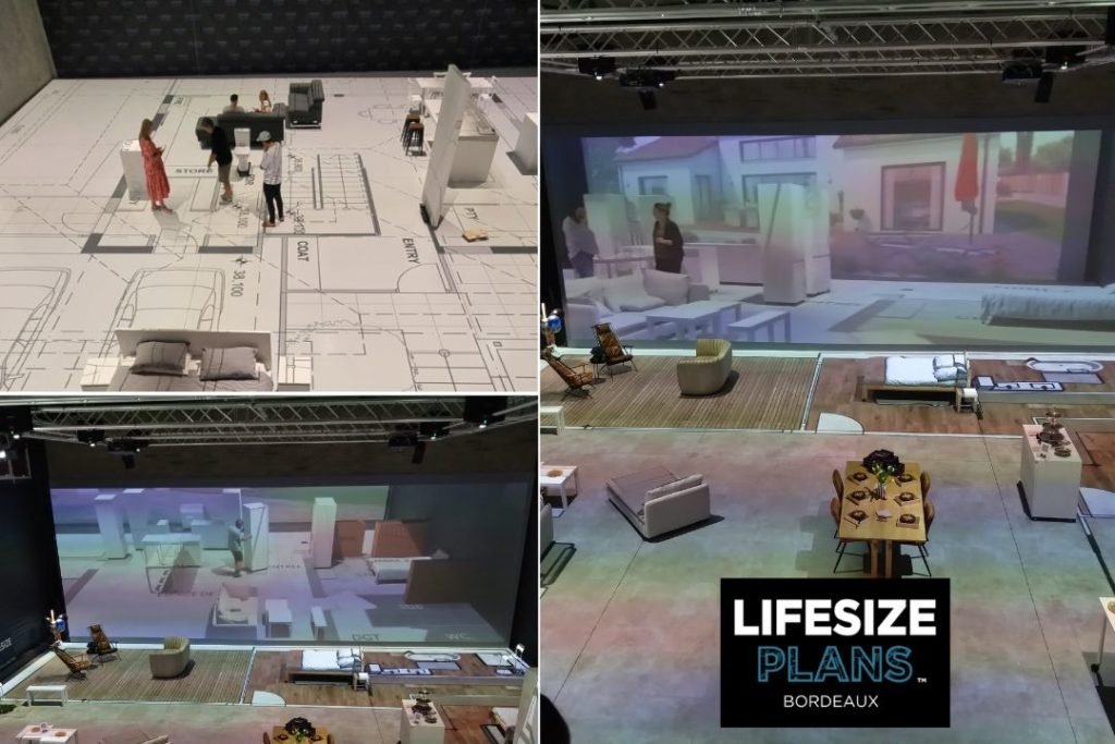
Referenz der Implementierung: Lifesize Plans Bordeaux (maßstabsgetreue architektonische Projektion)
Lifesize Plans Bordeaux ist ein praktisches Beispiel dafür, dass “1:1 verzerrungsfrei” kein Kalibrierungstrick ist, sondern eine Systemverantwortungsgrenze.
Das Projekt zielt auf eine maßstabsgetreue architektonische Erfahrung unter Verwendung von GeoBox Edge-Blending-Prozessor in Kombination mit einem großen Multiprojektor-Array (12 lichtstarke Christie DWU-Projektoren).
Was diese Umsetzung beweist:
- Eine Leinwand, ein Vertrag: Inhalt wird so produziert, dass er dem kombiniertes Seitenverhältnis der Anzeigefläche, so dass das System nie eine ungleichmäßige Skalierung benötigt (kein Stretching/Squashing).
- Ausgangsseitiger Determinismus: GeoBox in Vollbild Verhalten bleibt die “Füllung” vorhersehbar, während die geometrische Ausrichtung nachgelagert in der technischen Ebene angewendet wird.
- Wiederholbarkeit, nicht Heldenarbeit: Nach der Validierung mit einfachen Geometrie-/Maßstabsprüfungen wird das Setup als abrufbares Profil gespeichert, so dass das System nach einer Wartung oder einem Quellenwechsel wieder in denselben verzerrungsfreien Zustand versetzt werden kann.
Wenn Sie sehen möchten, wie diese Logik in einer realen Architekturvisualisierungsumgebung umgesetzt wird, lesen Sie die Fallstudie: “Revolutionierung der Architektur Visualisierung: Lifesize-Pläne Bordeaux.”