
Projection cylindrique à 360° : guide pratique de conception géométrique
Utilisation de la déformation 30% comme référence GeoBox
Pour la conception préliminaire d'une projection cylindrique, La déformation 30% peut servir de référence pratique pour la correction géométrique de GeoBox. (Cliquez ici pour Série GeoBox Edge blending et Warping)
Il ne faut pas considérer cette valeur comme une limite absolue. La capacité de correction réelle dépend également du rapport de projection du projecteur, de la distance de projection, des caractéristiques de l'objectif et de la géométrie d'installation.
La référence 30% a pour objectif d'identifier les cas où une conception présente des contraintes géométriques importantes et doit donc faire l'objet d'une vérification avant son installation.
1. Conversion de la courbure d'un cylindre en pourcentage
Pour une surface circulaire :
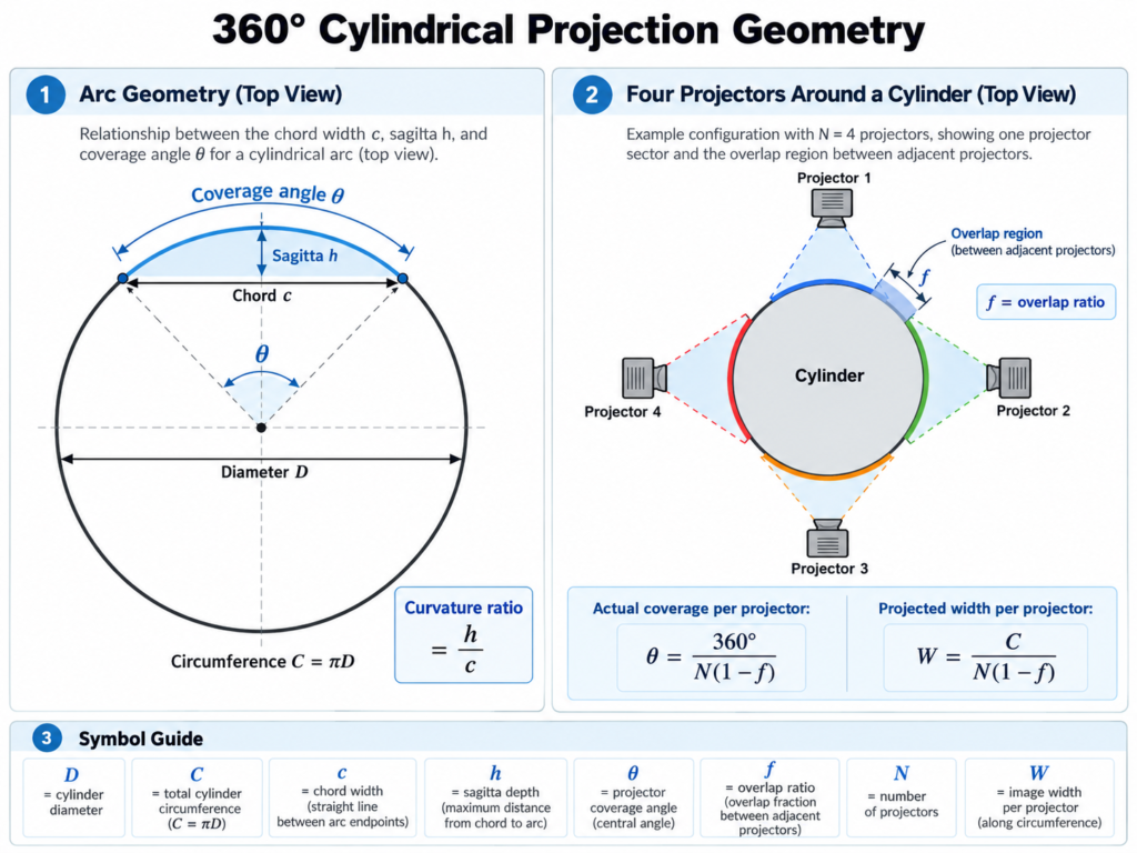
- Accord (do) = distance en ligne droite entre les deux bords de la surface projetée
- Sagitta (h) = profondeur maximale entre la corde et la surface courbe
Le rapport de courbure est : h/c
Pour un arc de cercle dont l'angle de couverture est θ
h/c = 1/2 tan(θ/4)
On obtient ainsi :
| Couverture du projecteur | Rapport de courbure |
|---|---|
| 90° | 20.7% |
| 100° | 23.3% |
| 110° | 26.0% |
| 120° | 28.9% |
| 124° | ~30% |
| 127° | ~31% |
Un seul projecteur couvrant environ Une valeur comprise entre 120 et 125° pour un cylindre se situe donc déjà proche de la plage de référence du 30%.
2. Nombre de projecteurs et couverture requise
En l'absence de chevauchement pour la fusion des bords, le nombre de projecteurs correspond à 360 degrés divisé par la couverture nominale par projecteur. Cependant, les projecteurs adjacents nécessitent un chevauchement pour permettre la fusion des bords. La documentation de GeoBox indique qu’une zone de chevauchement typique est d’environ 20–40% de l'image du projecteur individuel, selon l'application.
Utilisation de Chevauchement 20% à titre de valeur de conception préliminaire :
θ = 360° / N(1 - f)
où :
- N= nombre de projecteurs
- f= taux de chevauchement
Cela donne environ :
| Projecteurs | Couverture réelle avec un chevauchement de 20% | Rapport de courbure |
|---|---|---|
| 3 | 150° | ~38% |
| 4 | 112.5° | ~27% |
| 5 | 90° | ~21% |
| 6 | 75° | ~17% |
Cela fait que quatre projecteurs : un point de départ pratique pour de nombreux systèmes cylindriques à 360°. Trois projecteurs peuvent déjà dépasser la référence 30% une fois pris en compte le chevauchement normal lors de la fusion des images.
3. Avoir plus de projecteurs n'est pas toujours une bonne chose
L'ajout de projecteurs réduit l'angle de couverture et, par conséquent, diminue la déformation géométrique.
Cependant, cela réduit également la taille physique de l'image projetée par chaque projecteur.
Pour un cylindre : C = πD
et la largeur approximative projetée par projecteur est de : W = C/N(1 - f)
L'ajout de projecteurs supplémentaires réduit encore davantage la taille de chaque image. À ce stade, la limite ne réside peut-être plus dans la correction géométrique GeoBox, mais dans la distance minimale de mise au point et la taille minimale de l'image des projecteurs.
C'est pourquoi les très petits cylindres peuvent s'avérer peu pratiques, même lorsque l'on ajoute davantage de projecteurs.
Dans le cadre d'un projet antérieur, un cylindre de 50 cm de diamètre avait donc été agrandi afin d'obtenir un meilleur équilibre entre la correction de la courbure et l'optique du projecteur.
4. Rapport de projection et distorsion
Le rapport de projection a une incidence directe sur la distorsion cylindrique.
A course plus longue Cela permet de placer le projecteur plus loin du cylindre, ce qui rend les trajets lumineux plus parallèles. Cela réduit la distorsion sur les côtés de l'image et offre une plus grande marge de manœuvre pour la correction géométrique.
A course plus courte crée des trajets optiques plus divergents, ce qui accentue la distorsion sur les bords et augmente l'ampleur de la correction nécessaire.
La documentation de GeoBox précise également que les rapports de projection plus élevés entraînent moins de distorsion sur les écrans courbes, tandis que les projecteurs à ultra-courte focale ne sont pas recommandés pour ce type d'application.
5. Résultats des examens médicaux
Un essai cylindrique à échelle réduite a été réalisé à l'aide des éléments suivants :
- GeoBox M810
- un projecteur
- rapport de projection d'environ 1,0:1
- motif de test à quadrillage régulier
- contenu vidéo classique
Le résultat était le suivant :
Couverture d'environ 110°
La correction géométrique est restée dans une fourchette acceptable.
Couverture d'environ 120°
La majeure partie de la déformation cylindrique a tout de même pu être corrigée. Il subsistait toutefois une légère distorsion résiduelle près des bords extrêmes, visible à l'aide d'un motif de test en grille, mais difficile à remarquer lors d'une lecture vidéo normale.
Au-delà de 120°, le besoin de correction augmentait rapidement.
6. Procédure opérationnelle standard (SOP) pratique pour la projection cylindrique à 360°
Pour les nouveaux projets de projection cylindrique, le processus suivant peut être utilisé.
Étape 1 — Calculer la circonférence du cylindre
C = πD
Ce paramètre définit la largeur physique totale de l'image à 360°.
Étape 2 — Commencez par compter le nombre de projecteurs
Pour une projection à 360° :
- 3 projecteurs = minimum théorique
- 4 projecteurs = un point de départ pratique
- 5 à 6 projecteurs = exigences géométriques moindres
Étape 3 — Ajouter un chevauchement et vérifier la couverture
Pour un système classique à 360°, Le chevauchement entre les modèles 20–25% constitue un point de départ concret.
Avec quatre projecteurs, cela permet généralement de maintenir la couverture d'un seul projecteur dans les limites approximatives de la référence de déformation 30%.
Un chevauchement plus important peut s'avérer utile dans les cas suivants :
- il faut une image plus haute,
- une transition plus fluide est préférable,
- ou si une plus grande souplesse d'ajustement géométrique est nécessaire sur la surface courbe.
Si le chevauchement le plus important fait basculer le angle de couverture réel Si l'angle de couverture dépasse la plage de correction recommandée, envisagez d'augmenter le nombre de projecteurs afin de réduire l'angle de couverture et la déformation globale par projecteur.
Étape 4 — Vérifier la taille physique de l'image
Calculez la largeur approximative de la projection par projecteur :
W = C/N(1 - f)
Vérifiez ensuite que le projecteur et l'objectif sélectionnés permettent de projeter et de faire la mise au point sur une image de cette taille à la distance d'installation disponible.
Étape 5 — Vérifier le rapport de projection et la distance
Une course plus longue et une distance de projection plus grande réduisent généralement la distorsion cylindrique. Évitez d'utiliser un projecteur dont le rapport de projection est inférieur à 1,0:1 pour la projection cylindrique.
Étape 6 — Modifiez le design si nécessaire
Si la géométrie est trop agressive, pensez à :
- augmentation de la distance de projection (à l'aide de projecteurs dotés d'un rapport de projection plus élevé),
- augmentation du nombre de projecteurs,
- augmentation du diamètre du cylindre.
Conclusion
Pour une projection cylindrique à 360°, la première question ne devrait pas être :
Quelle capacité de warping le processeur peut-il offrir ?
Une meilleure séquence de conception est la suivante :
Diamètre du cylindre → nombre de projecteurs → chevauchement → angle de couverture → vérification de la déformation 30% → taille de l'image → rapport de projection
La référence de déformation 30% permet d'effectuer une première vérification utile de la faisabilité.
Si la correction requise avoisine ou dépasse cette plage, la solution privilégiée consiste généralement à améliorer la géométrie optique en augmentant la distance de projection, le nombre de projecteurs ou le diamètre des cylindres, avant de demander au processeur de compenser davantage de distorsion.
Une bonne projection cylindrique commence par une géométrie optique facile à gérer. GeoBox apporte ensuite la précision nécessaire pour la déformation finale, l'alignement et la fusion des bords.