
Projection Mapping on an Irregular 3D Object with GeoBox M802EX
A Two-Projector Volcano Mapping Installation at UNICAL
Projection mapping is not limited to flat walls or building façades. Museums, universities and exhibition designers increasingly use projected content to animate terrain models, sculptures and other irregular physical objects.
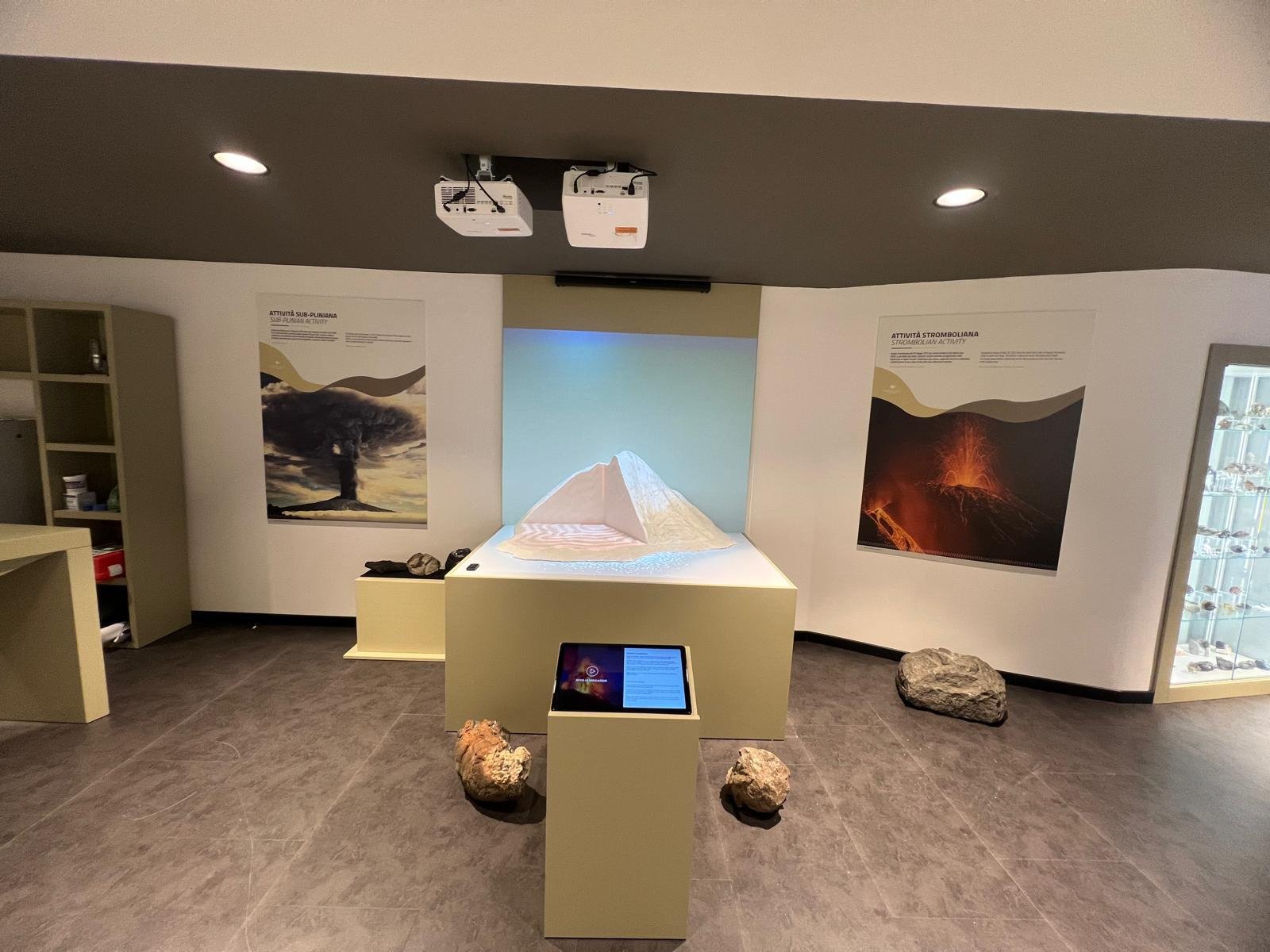
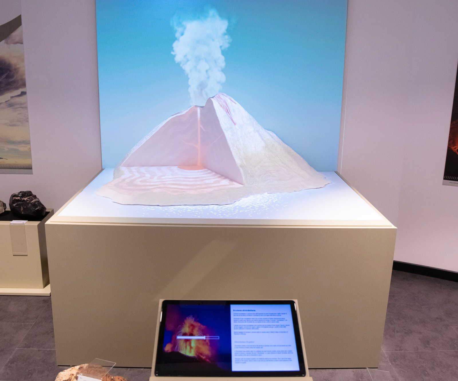
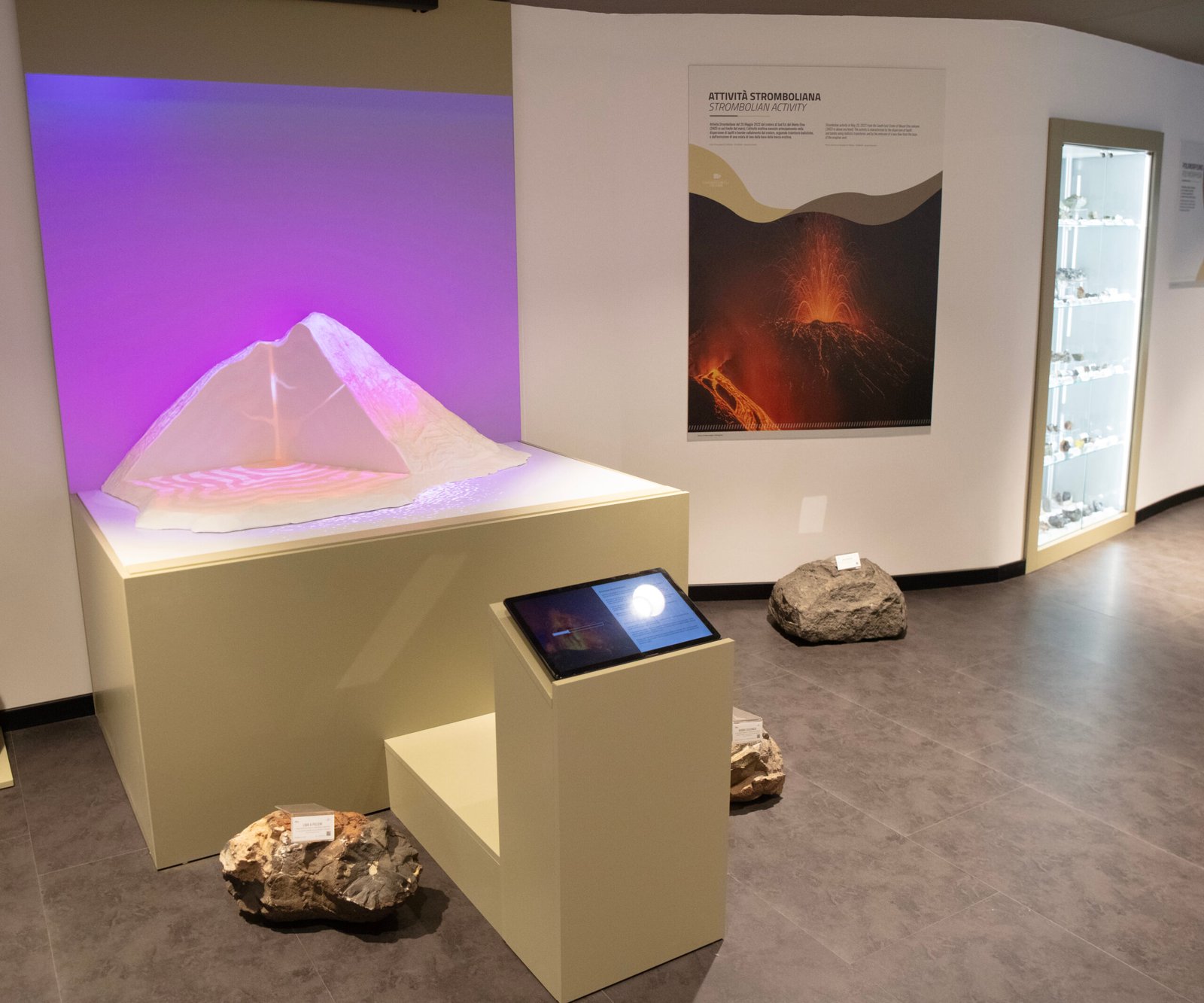
At the University of Calabria, also known as UNICAL, Italian system integrator DOCONLINE created a projection mapping installation around a detailed volcano model. Two projectors were used to cover the model’s slopes, ridges and crater while extending the visual content onto the background wall.
GeoBox M802EX was selected for image distribution, geometry correction and projection mapping. Although this was DOCONLINE’s first use of GeoBox for this type of application, its engineering team successfully completed the installation with technical guidance from the GeoBox team.
The Engineering Challenge
Unlike a conventional screen, the volcano model included:
- Sloped and elevated terrain
- A recessed crater
- Irregular outer boundaries
- Different depths between the model and the background wall
Basic keystone or four-corner correction could define the overall image area, but it could not align the content with all the internal contours of the model.
Projector positioning was equally important. Raised sections of the volcano could create shadows, while the model and background wall required different geometric adjustments. Digital warping could reshape the image, but it could not compensate for unsuitable projector angles or physical obstruction.
Why GeoBox M802EX Was Selected
M802EX is the dual-channel model in the GeoBox M800EX family. It can receive a source image, distribute the required portions to two projector outputs and apply independent geometry correction to each channel. The same product family also supports the use of projection-mapping patterns created and uploaded through the GWarp3 PC tool.
For the UNICAL installation, this allowed DOCONLINE to work with one complete visual composition rather than managing two entirely separate playback systems.
The architecture provided several practical advantages:
- Both projectors used the same source signal
- Separate media-player synchronisation was not required
- Image division could be refined during installation
- Projection geometry could be adjusted independently of content production
- Mapping and alignment settings could be stored in the GeoBox hardware
This last point is important for permanent installations. Once the mapping patterns and geometry settings have been saved in the unit, the PC used for configuration is no longer required for normal operation.
From the Physical Object to a Mapping Pattern
The M800EX projection-mapping procedure begins before any pattern is uploaded to the processor.
For an irregular object, the recommended method is to observe the target from the same position as the projector lens. A reference image can then be taken from that viewpoint and used to create a black-and-white mapping pattern representing the exact area where content should appear.
In practical terms, the workflow is:
- Position the projector and establish the intended coverage.
- Capture the physical object from the projector’s viewpoint.
- Create a monochrome pattern based on the object’s visible silhouette.
- Size the pattern according to the projector resolution and the portion of the projected area occupied by the object.
- Upload the pattern into GeoBox through GWarp3.
- Preview the result before saving it to the hardware.
This approach is different from using geometry correction alone.
Geometry correction reshapes the complete rectangular image. The mapping pattern defines where the source should remain visible and where it should be masked. Together, these two functions allow the image to follow both the position and the outline of an irregular physical object.
Building the Projection from the Outside In
Once the projectors and mapping patterns had been established, the geometry could be refined.
The M800EX setup procedure recommends completing alignment progressively, beginning with basic four-corner control and then moving to denser warp grids only when required. This prevents the installation engineer from introducing excessive local distortion before the overall image structure is correct.
1. Establish the Overall Projection Boundary
The first task was to place the projected image in the correct physical area.
At this stage, the engineers focused on:
- The outer boundary of the model
- The overall image size
- The relative positions of the two projector channels
- The boundary between the model and the background wall
The objective was not yet to match every ridge or crater detail.
2. Align the Major Terrain Features
After the overall boundary had been established, the engineers could progressively refine the internal geometry.
Only after these elements were stable did it make sense to correct smaller local details.
3. Refine the Mapping Pattern Position
The mapping pattern was then checked against the physical outline of the volcano.
If the pattern did not sit precisely over the intended object, its position could be refined through geometry correction.
4. Complete the Two-Projector Relationship
Once both channels had been corrected individually, DOCONLINE could refine the scale, position and transition between them.
This order made troubleshooting more manageable. A remaining mismatch could be identified more clearly as:
- A projector-positioning issue
- A geometry issue
- A mapping-pattern issue
- A source-distribution issue
Project Result
DOCONLINE successfully completed the two-projector projection mapping installation for the UNICAL volcano model.
The result was achieved through the system integrator’s engineering work in projector placement, image alignment and on-site calibration. GeoBox M802EX provided the hardware tools needed to distribute, mask and geometrically correct the image.
The completed system used one visual composition distributed across two projectors. The image followed the principal contours of the volcano model and continued onto the background wall as a unified presentation.
Applications Beyond Terrain Models
The same GeoBox approach can be applied to:
- Museum terrain and city models
- Architectural scale models
- Scientific and educational exhibits
- Sculptures and art installations
- Stage scenery and physical props
- Industrial product models
- Themed attractions
For irregular-object projection, the key is not simply the number of available warp points. A successful installation requires the correct sequence:
- Position the projectors.
- Create the mapping pattern.
- Establish the overall image geometry.
- Refine the surface alignment.
- Complete the multi-projector relationship.
- Save and back up the final settings.
The UNICAL project demonstrates how GeoBox can provide a dedicated and maintainable hardware layer for projection mapping on complex physical objects.